10-bit vs. 16-bit ADC - 1:30 PM 1/10/2019
Mayhew Extended ADC shield on Digilent Chipkit uC32.
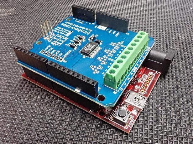
 Initial test of the LTC1859 16-bit ADC on Mayhew Lab's Extended ADC shield.
This shield works with the uC32 and passes through the signals on pins 3-7
needed to drive the C7041 CCD head. It was practically PnP for this application.
No signal conditioner is being used (although this should always be checked).
Fluorapatite:
Initial test of the LTC1859 16-bit ADC on Mayhew Lab's Extended ADC shield.
This shield works with the uC32 and passes through the signals on pins 3-7
needed to drive the C7041 CCD head. It was practically PnP for this application.
No signal conditioner is being used (although this should always be checked).
Fluorapatite:

 The solder jumper SJ7 was set to 3.3V to match uC32
logic levels even though uC32 says it can handle 5V.
The 100kHz demo was modified to use uC32's PORTD,
and use a 1044 sample frame (CCD frame), and integrated
with test1006s.ino.
The Raman shift scale is probably out of calibration.
The plot appears attenuated.
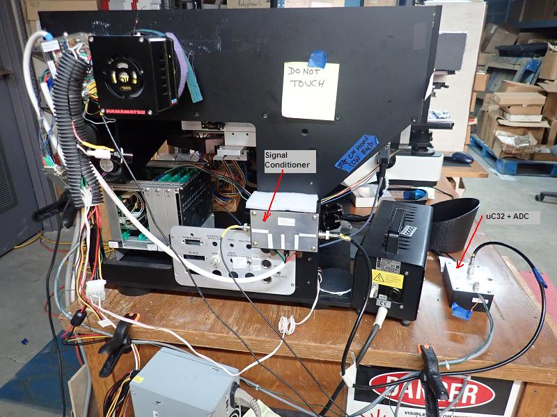
This is no doubt due to the signal conditioner which
rescales the 0-10 signal to 0-3.3V needed for the uC32's ADC.
Quick solutions:
*bypass the signal conditioner
*change the 16-bit ADC to use 0-5V range with some loss of resolution.
Here's the raw 16 bit spectrum without using the signal conditioner:
The solder jumper SJ7 was set to 3.3V to match uC32
logic levels even though uC32 says it can handle 5V.
The 100kHz demo was modified to use uC32's PORTD,
and use a 1044 sample frame (CCD frame), and integrated
with test1006s.ino.
The Raman shift scale is probably out of calibration.
The plot appears attenuated.
This is no doubt due to the signal conditioner which
rescales the 0-10 signal to 0-3.3V needed for the uC32's ADC.
Quick solutions:
*bypass the signal conditioner
*change the 16-bit ADC to use 0-5V range with some loss of resolution.
Here's the raw 16 bit spectrum without using the signal conditioner:
 The laser line is clipped with a ragged top probably because...?
Broad laser line indicates misalignment...
The gaps in the plot are from separate CCD frames not splicing well.
The optics is not optimally aligned but it wasn't changed
between these ADC tests.
Realignment will have to be done yet again...
The laser line is clipped with a ragged top probably because...?
Broad laser line indicates misalignment...
The gaps in the plot are from separate CCD frames not splicing well.
The optics is not optimally aligned but it wasn't changed
between these ADC tests.
Realignment will have to be done yet again...