Signal Conditioner for the ADC
The signal coming from the detector needs to be linearly matched to the ADC.
Scaled (multiplication) and D.C. offset shifted (addition).
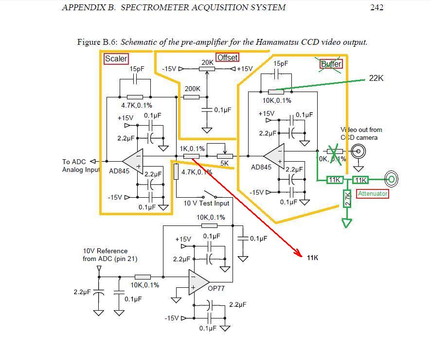
In Marc Baril's Thesis on Luminescence there's a useful circuit for detector signal
scaling/offsetting in Appendix B.
The 1K resistor can be changed to 11K (red) which allows the 10V output from the C7041 head
to be scaled down to 3.3V range suitable for the Chipkit uC32's 10-bit ADC,
but using the op-amp as an attenuator this way is not recommended.
Instead (green), a passive divider is recommended that keeps the op-amp stable:
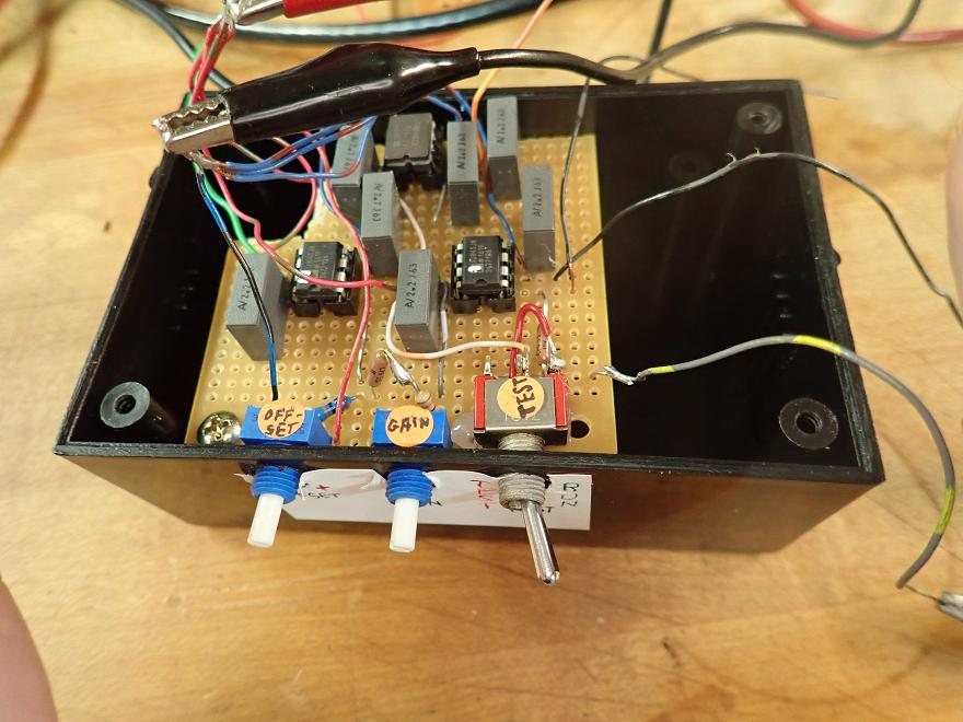
 There's probably a better way.
Did not have the 11K, 2.7k resistors handy.
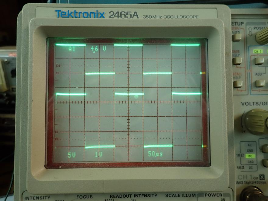
Instead, adding 10k to the 1k. Not seeing any problems on the scope
(even with sine, triangle at higher frequencies):
There's probably a better way.
Did not have the 11K, 2.7k resistors handy.
Instead, adding 10k to the 1k. Not seeing any problems on the scope
(even with sine, triangle at higher frequencies):
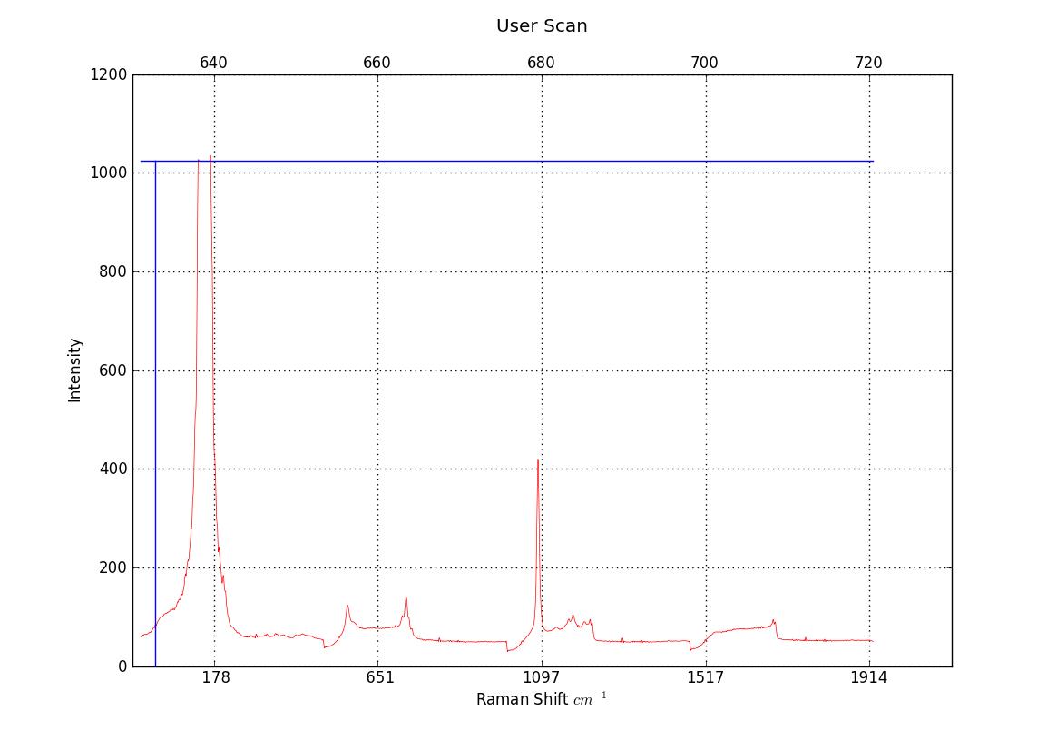
 So far this seems to working good (better), but as can be seen below
new problems have arisen ("one step forward, two steps backward").
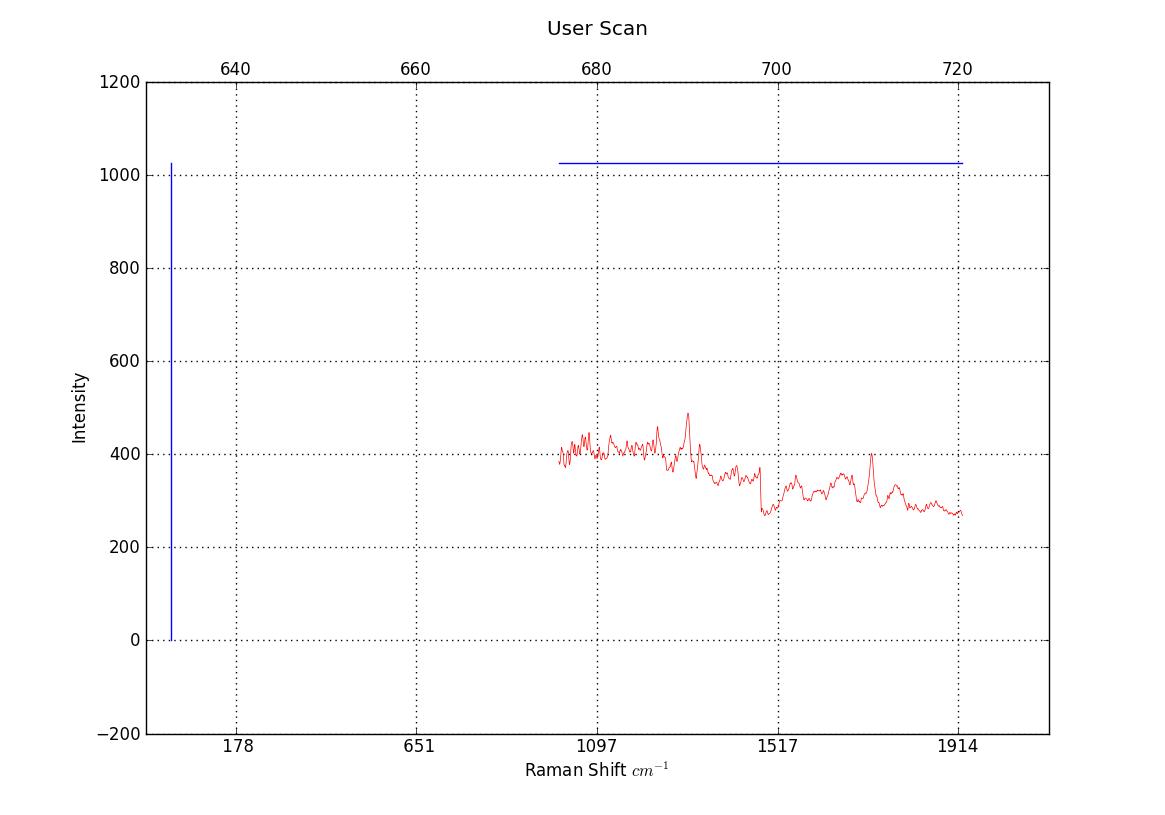
The following (633nm) spectra have uncalibrated scales and each
CCD frame is offset incorrectly from the previous frame.
This is probably due to a combination of larger CCD sensor and an
imperfect replacement of the spectrograph's scuffed exit mirror.
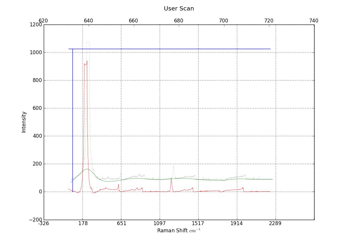
Poor quality UNCALIBRATED (633nm) spectra, but characteristic peaks are definitely present.
Fluorapatite - Cerro de Mercado, Durango, Mexico:
So far this seems to working good (better), but as can be seen below
new problems have arisen ("one step forward, two steps backward").
The following (633nm) spectra have uncalibrated scales and each
CCD frame is offset incorrectly from the previous frame.
This is probably due to a combination of larger CCD sensor and an
imperfect replacement of the spectrograph's scuffed exit mirror.
Poor quality UNCALIBRATED (633nm) spectra, but characteristic peaks are definitely present.
Fluorapatite - Cerro de Mercado, Durango, Mexico:
 Ibuprofen:
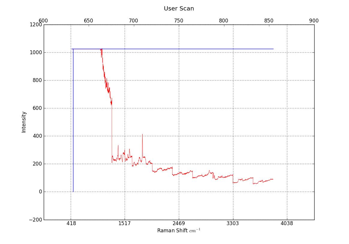
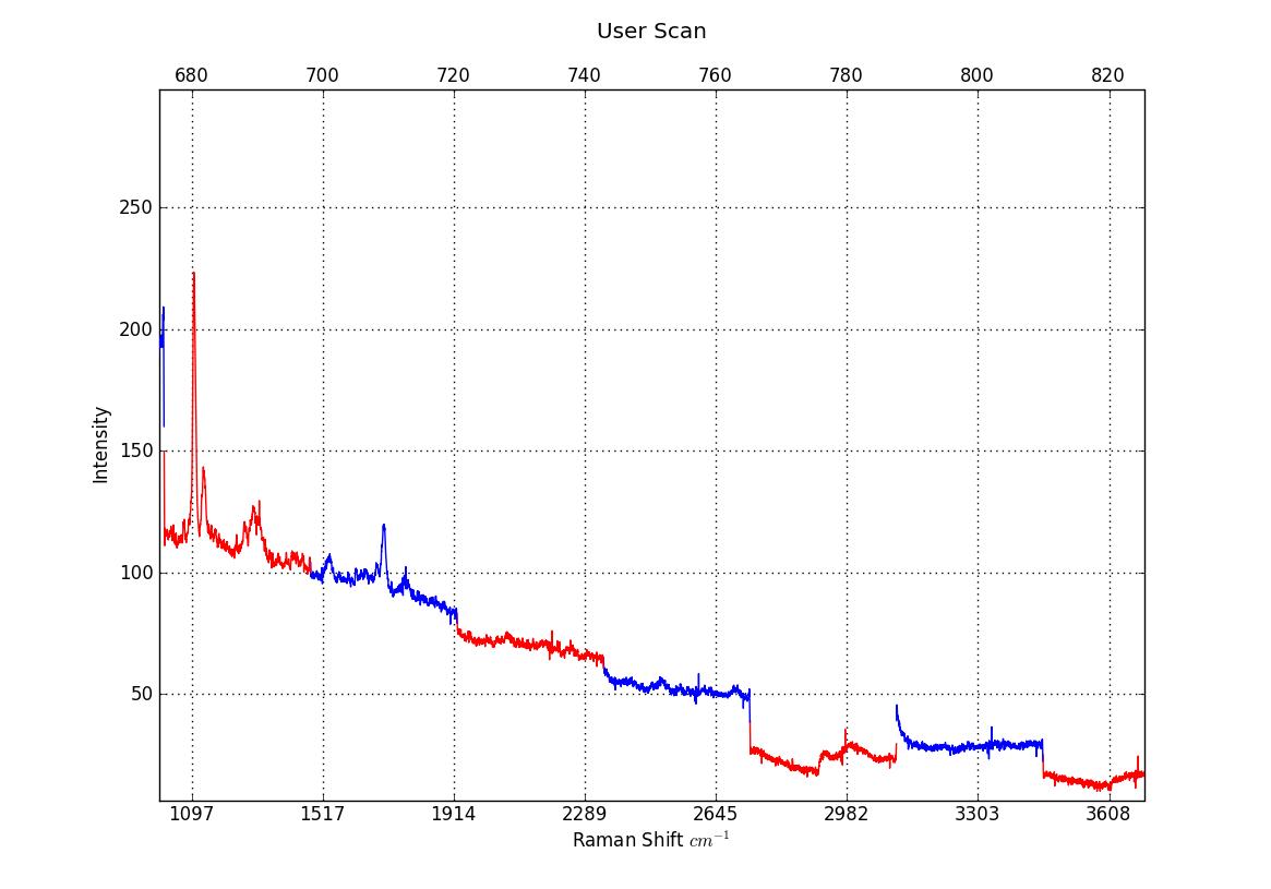
 Aspirin (extended range):
 Synthetic silicon (Motorola):
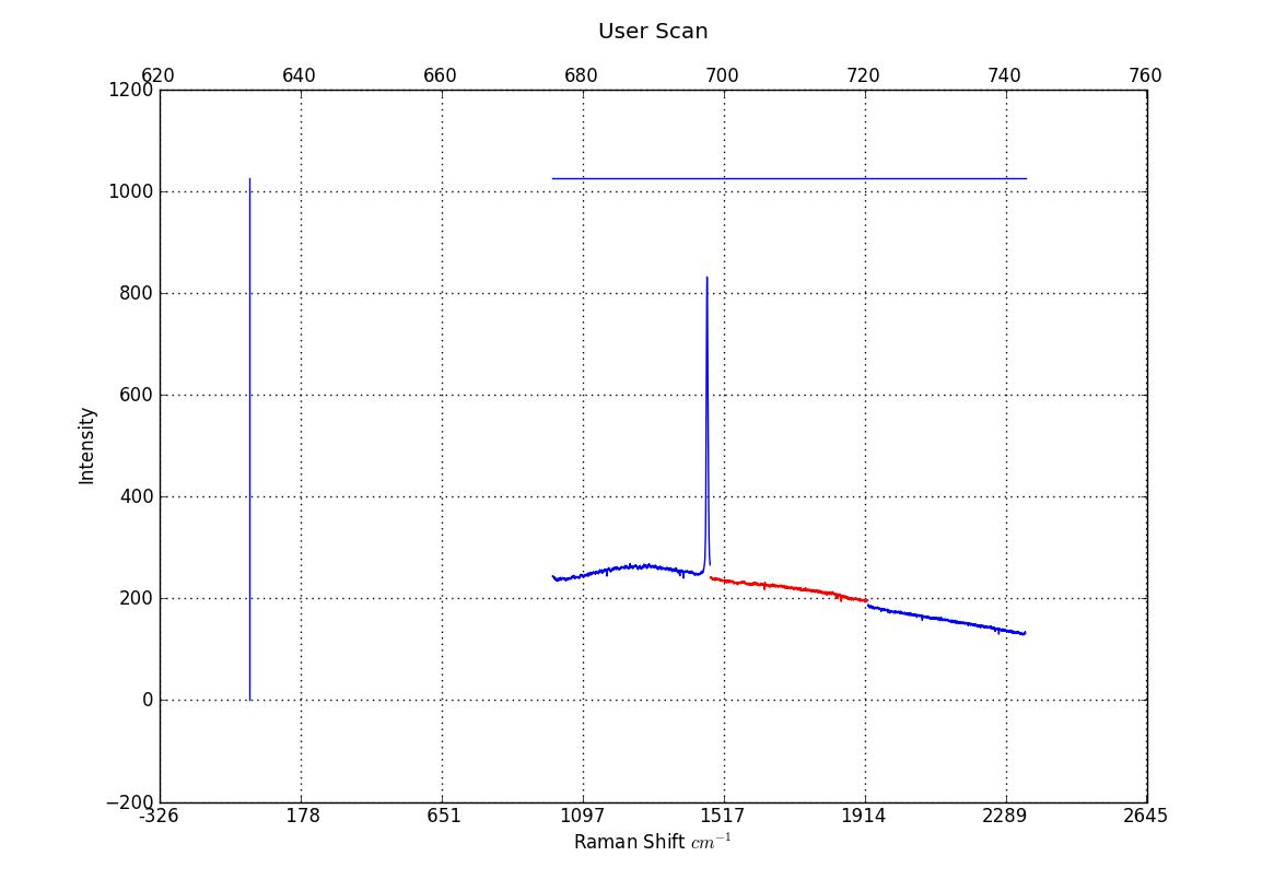
 polystyrene (plastic spoon):
 Diamond (synthetic) Japan:
 Spessartine:
 Calculations:
Goal: pick the appropriate ADC bit depth for the detector.
Dynamic range (dB) = SNR (dB) = 20*log(full well capacity/readout noise)
S7031-1006S sensor:
Full well capacity: 1,000,000e- * 2.2 uV/e- = 2.2V
Line binning dynamic range: 125000 = 1000000e-/8e- (RMS)
V=eV/(Q/k), Q=1000000, k=1.602176565E-19
V=1000000/(1000000/1.602176565E-19) = 16V
Dynamic range: 125000 = 102dB
Required ADC:
bits >= 102/6.02 (>= 17 bits)
C7041 head:
Outputs 10V (actual) for full well capacity.
The number of electrons in full well for line binning mode is, 1,000,000e-
Conversion gain is 15uV/e-.
Full well capacity: 1,000,000e- * 15uV/e- = 15volts
Readout noise 20 e- RMS.
Dynamic range is given as "33333" (should be 50000?) = 90dB
Required ADC:
bits >= 90/6.02 (>= 15 bits)
Improving sensitivity further with higher resolution ADCs:
The 16-bit AD7667 might be an acceptable solution.
Input: 0-2.5VDC. Max 1Msps.
but this ADC needs an Arduino Mega for all the pins it uses
and the Mega might not be fast enough. Dave Allmon
has abandoned this approach. The Digilent MAX32 appears to be a 32 bit MEGA...
The 24-bit ADS1252 requires a CMOS clock signal. uC32 timer2/OC1 can output
a 50% duty cycle PWM on pin 3 but it shows Gibbs phenomena (think: leaky black holes)
on the edges and seems to get very distorted above 2MHz and probably needs
a Schmitt trigger to clean it up.
This ADC is unlikely to give full 24-bit resolution without shielding, decoupling, &c.
Need to brush up on PCB layout skills.
It claims to give 19-bits up to 41.67KHz data rate (16MHz CLK) but doesn't
seem to specify where 24-bit performance can be expected.
WARNING: the ADS1252 datasheet is misleading.
Be sure to also read SLAA242 - Interfacing the ADS1251/52 to the MSP430F449, May 2005
In "Table II Digital Timing", "CLK" is NOT the system clock on pin 4.
It is actually "1000000000/MCLK".
MCLK is the modulation clock (=CLK/6).
ADC types (source: ti.com):
Calculations:
Goal: pick the appropriate ADC bit depth for the detector.
Dynamic range (dB) = SNR (dB) = 20*log(full well capacity/readout noise)
S7031-1006S sensor:
Full well capacity: 1,000,000e- * 2.2 uV/e- = 2.2V
Line binning dynamic range: 125000 = 1000000e-/8e- (RMS)
V=eV/(Q/k), Q=1000000, k=1.602176565E-19
V=1000000/(1000000/1.602176565E-19) = 16V
Dynamic range: 125000 = 102dB
Required ADC:
bits >= 102/6.02 (>= 17 bits)
C7041 head:
Outputs 10V (actual) for full well capacity.
The number of electrons in full well for line binning mode is, 1,000,000e-
Conversion gain is 15uV/e-.
Full well capacity: 1,000,000e- * 15uV/e- = 15volts
Readout noise 20 e- RMS.
Dynamic range is given as "33333" (should be 50000?) = 90dB
Required ADC:
bits >= 90/6.02 (>= 15 bits)
Improving sensitivity further with higher resolution ADCs:
The 16-bit AD7667 might be an acceptable solution.
Input: 0-2.5VDC. Max 1Msps.
but this ADC needs an Arduino Mega for all the pins it uses
and the Mega might not be fast enough. Dave Allmon
has abandoned this approach. The Digilent MAX32 appears to be a 32 bit MEGA...
The 24-bit ADS1252 requires a CMOS clock signal. uC32 timer2/OC1 can output
a 50% duty cycle PWM on pin 3 but it shows Gibbs phenomena (think: leaky black holes)
on the edges and seems to get very distorted above 2MHz and probably needs
a Schmitt trigger to clean it up.
This ADC is unlikely to give full 24-bit resolution without shielding, decoupling, &c.
Need to brush up on PCB layout skills.
It claims to give 19-bits up to 41.67KHz data rate (16MHz CLK) but doesn't
seem to specify where 24-bit performance can be expected.
WARNING: the ADS1252 datasheet is misleading.
Be sure to also read SLAA242 - Interfacing the ADS1251/52 to the MSP430F449, May 2005
In "Table II Digital Timing", "CLK" is NOT the system clock on pin 4.
It is actually "1000000000/MCLK".
MCLK is the modulation clock (=CLK/6).
ADC types (source: ti.com):
| Type | sps Rate | Res |
| SAR | <2M | <=18-bit |
| Delta-Sig | <20M | <=24-bit |
| Flash | <500M | <=10-bit |
| Pipeline | <200M | <=16-bit |