Area Scanning
S7013-1006S Hamamatsu CCD
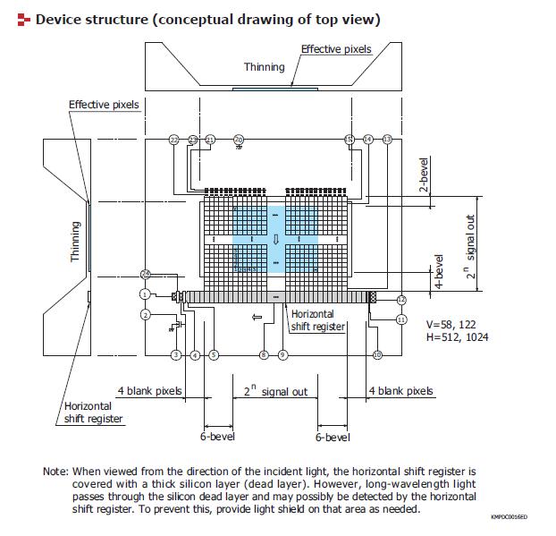
The Hamamatsu S7031-1006S is a full-frame transfer (FFT) linear-array CCD.
It has a 1044x64 pixel array, but only 1024x58 of those pixels
are useful for the spectrum. The vertical columns of pixels are
usually "line-binned": they are vertically summed and the sum row
is dumped to the ADC as the spectrum.
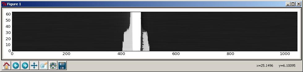
Line-binning can be disabled and the full 1024x58 pixel image frame
can be dumped. This is particularly useful if you want to see
how well the slit image (the laser light after it passes through the
spectrograph's entrance slit) is aligned with the CCD pixels.
Aligning the slit image with the CCD is as important as focusing
the slit image on the CCD and being sure the slit's image plane is
not slanted with respect to the CCD.
Hamamatsu warns the CCD shutter should be closed during area readouts
to prevent smearing. There seems to be some vertical asymmetry in
these images which is not good. Ideally each row should be identical.
The 1044x64 pixel assignments:
First 10 columns = 4 blank pixels + 6 bevel pixels
Last 10 columns = 6 bevel + 4 blank
First 2 rows = bevel pixel lines
Last 4 rows = bevel pixel lines
All other pixels are active pixels.
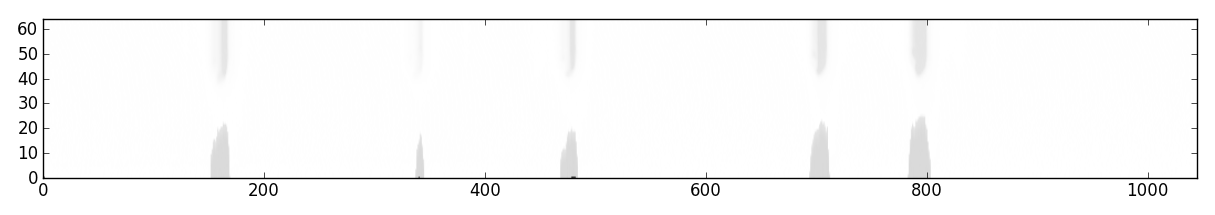
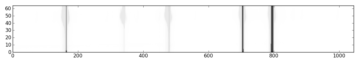
 These bevel/dark pixels are not visible the way I expected.
These images were taken with lengthing exposure times but for
some reason they do not get progressively "brigher" using
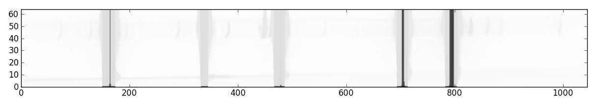
the default pyplot colormap. The second image shows the
"gray" colormap being used which seems less revealing than
the default colormap. The B&W image was the same exposure time
as the first image. It is not good that the colormap choice
should reveal very different information.
I'll redo these images later and save the actual jpegs instead
of screen snapshots so they can be dissected at the pixel level.
These bevel/dark pixels are not visible the way I expected.
These images were taken with lengthing exposure times but for
some reason they do not get progressively "brigher" using
the default pyplot colormap. The second image shows the
"gray" colormap being used which seems less revealing than
the default colormap. The B&W image was the same exposure time
as the first image. It is not good that the colormap choice
should reveal very different information.
I'll redo these images later and save the actual jpegs instead
of screen snapshots so they can be dissected at the pixel level.

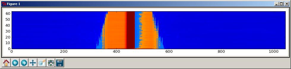

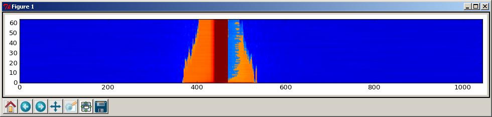
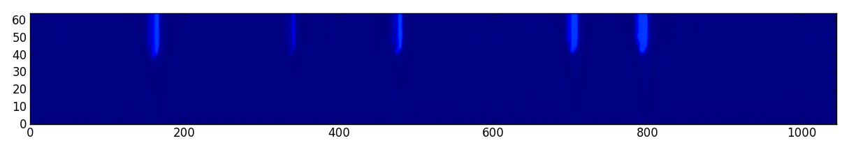
Neon peaks around 585.2nm (scales show pixel numbers).
Test:
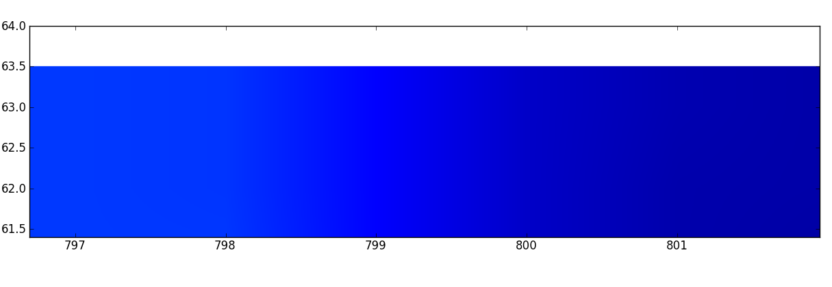
 Zoomed in on top edge. Pixels not visible.
How to turn off interpolation?:
Zoomed in on top edge. Pixels not visible.
How to turn off interpolation?:
 Using "greys" colormap:
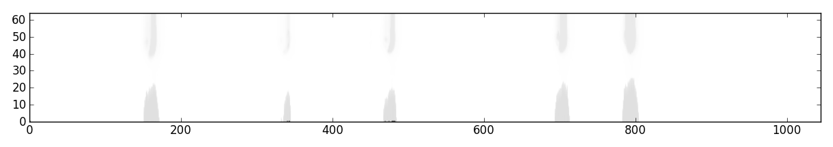
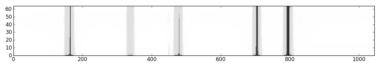
 Setting vmin and vmax:
 Default interpolation:
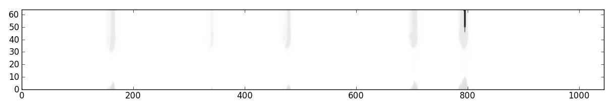
 Adjust CT focus mirror:
 Adjust CT focus mirror:
 Adjust CT focus mirror:
 Adjust CT focus mirror:
 Adjust CT focus mirror:
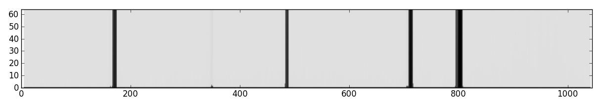 Flaring at the bottom of the lines might be caused
by full-slit illumination. In actual operation the slit
will only be partially illuminated by a beam spot from the
microscope objective.
Flaring at the bottom of the lines might be caused
by full-slit illumination. In actual operation the slit
will only be partially illuminated by a beam spot from the
microscope objective.