To do (not necessarily in this order)
1:54 PM 10/28/2020
HOA2001-1 Schmitt-trigger photo-interrupter on the ND sled failed.
Obsolete part. Trying OPB970T55 and OPB460T11.
The 460 has a pullup output, but a smaller aperature.
The 970 has totem pole output; is probably the best replacement choice.
2:30 PM 3/16/2020
Added Adafruit Arduino Motor Shield V2 address #1 to control shutter motors 1-3.
Working.
7:53 AM 2/12/2020
Right-angle injection of the 532nm 200mW laser by the 70/30 beamsplitter
produces a non-flat intensity profile. The oblique-injection used by
Horiba is probably justified by moving the BS back which presents a
flatter surface to the beam reflected back from the objective?
2:48 PM 2/7/2020
Adjusted the TEC on Melles-Griot 532nm by turning CCW to reduce
temperature blue-shifting the peak so it sits further left
on the Tiger 532nm LP edge filter's cut-on slope.
The crocoite spectrum looks promising with good match on the RRUFF database.
But too many vibrations in the warehouse are disturbing the
hot-glued setup. I need to tap some holes and bolt down the
optics holders. The 70R/30T beamsplitter works better than
the 50/50 pellicle.
8:01 AM 10/25/2019
Had too much trouble trying to use the razor dll directly.
Currently using the same method as CrystalSleuth does to access the .dll.
This works okay. The result is two samples less than the input file.
Messed up the alignment yesterday while trying to get sharper peaks.
Focusing (by moving CCD in/out) did not work as usual.
Investigating...
2:23 PM 10/21/2019
Razor's baseline correction is running but crashes for some reason
when run in labram106.py.... very finicky about the input data.
Needs to be odd number of samples, and something else...
8:29 AM 10/4/2019
Have to figure out if the 532.8nm laser can be tuned up to 532.0nm
by cooling so it will be fully attenuated by the 532.0LP edge filter.
Scalloping problems seems to have been rectified by correctly positioning
the new exit mirror. The yaw and/or roll between the slit and the linear CCD
cause the intensity variations
Currently "ghostbusting" the CCD by doing several zero-exposure-time reads
with the shutter closed. This wastes the ghost images which contain some
electrons in the bins left-over from the last readout. Those electrons
do reflect the profile of the last spectrum readout (which is how they
were noticed in the first place) and should probably be integrated with
the readout buffer. So maybe I'll raise these ghosts from the dead and
add them into the buffer; spectres for the spectrum.
11:21 AM 9/24/2019
v7 harness works. The problem was the multistranded wire.
v7 uses copper telephone wire instead, same as v2.
The new 532nm LP edge filter looks good, but have n't yet got it to generate
any spectra...
The "scalloping" problem is definitely from the new exit mirror.
3:10 PM 9/6/2019
v2 wiring harness works.
v5 has problems, the DVI twisted pair isn't working,
probably needs separate coax like v2...
9:41 AM 8/8/2019
The problem with the CCD's TEC is that it is on the same ground as the
COOL digital signal. The CCD's Fan is on a separate ground so it should
not be used with the same power supply as the TEC. This requires a third
power supply unless I can determine which if any of the Aramis PSU's
5V supplies can handle the TEC's 2.5 amp requirement.
Working now on Version 4 of the wiring harness which uses a more heavily
shielded DVI cable.
10:55 AM 7/16/2019
Slit edges were not very good. Reversed them to use their other side.
Install a first-surface mirror in the spare slot on the grating turret
for testing purposes.
8:34 AM 7/11/2019
Version 3 of the "spinal cord" (the main electrical harness servicing the detector and oriental motor controller)
is installed. Seems to be working okay.
Software needs a lot of work; too many recent changes has made it unstable again.
Try to replicate some of Alian Wang's and DeRochette's work.
2:07 PM 6/25/2019
The wavelength calibration problem is definitely a calculation error.
It goes away when you do a full scan (which is what is used in a neon calibration
scan). Scanning a sub-range will introduce the shift.
9:51 AM 6/22/2019
The improved wiring harness has been finished.
With the improved shielding and grounding a considerable reduction
in CCD noise is noticed. The priority now is to figure out why
the wavelength calibration is being skewed again. It might be
from deactivating the grating turret brake (I did that to avoid
burning out the motor before I investigated the specifications)...
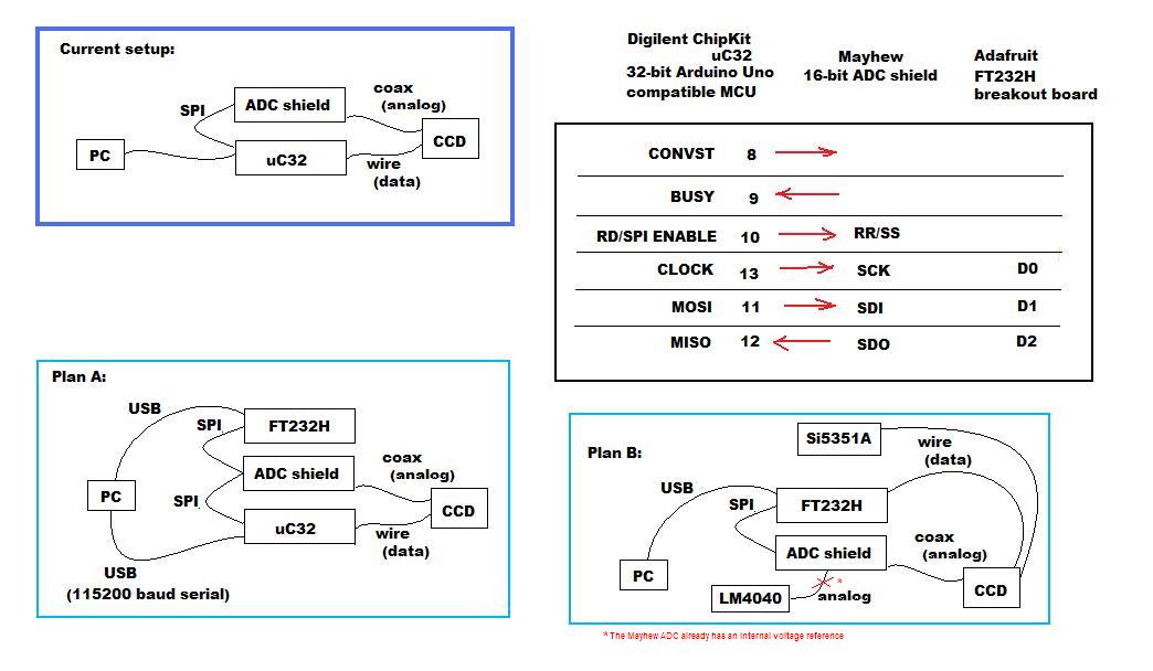
10:05 AM 5/13/2019
Using the ICSP (In Circuit Serial Programming) connector
avoids any confusion between different SPI wirings of the MPU boards
(same ICSP pinout is used for uC32 and Max32, but their board pins differ).
Goal:
Upload slave code to the Max32.
Power the Max32, via USB probably okay.
Plug the FT232H into the Mayhew shield's ICSP connector.
Use python as SPI master to talk to the Max32.
Write SPI slave code to control the Max32 and C7041 CCD head via python-SPI
rather than Arduino's Serial.
This slave code will replace Mayhew7.ino and should support high speed
spectral acquisition at video frame rates for line-binned spectra
(1044 pixels/frame, including darks and bevels).
Limited by the Mayhew ADC: 100,000(pixels/sec)/(1044 pixels/frame) = 95.785 frames/sec
For FFT, full frame transfers (1024x58 pixels, active pixels only)
the frame rate should be: SPI_transfer_rate/(2*1024x58 bytes)
where Adafruit gives max SPI_transfer_rate=30MHz (max_speed_hz);
so the frame rate=252.559 frames/sec but...
The frame rate limiting factor is then limited the speed of the digitization by
the Mayhew's LTC1859 16-bit ADC shield on analog video read out from C7041 CCD head.
The Mayhew shield doc says it can handle 100ksps max = 1024*58/100k = 1.68 frames/sec.
Actually, it's even less since the Mayhew must digitize the non-active pixels so
framerate=0.668 frames/sec:
further constraints from Hamamatsu C7041/S7031-1006S assuming 1MHz clock rate
(clock rate being used now:250kHz):
**minimum** integration time (exposure + readout) computations:
c7041 head w/S7031-1006S CCD with 1MHz clk
line binning mode (1044 pixels)
clk=1MHz
tb=16us/pixel //line binning op time = 1/(1/16 * clk)
Nv=64 //vertical pixels (including 6 bevels/isolations)
tt=2us // charge transfer time to horizontal register
tr=4us/pixel //readout time/pixel = 1/(1/4 * clk)
Nh=1044 // horizontal pixels (incliding 8 blanks and 12 isolation)
tend=4us // time interval of EOS (End Of Scan)
tscan=(tb*Nv)+tt+(tr*Nh)+tend
= (16us/pixel * 64pixels) + 2us + (4us/pixel * 1044pixels) + 4us
= 5.206ms/frame = 192.086055 frames/sec
area scanning mode (1044x64 pixels)
tscan=((tb+tt+(tr*Nh))*Nv+tend
=((16us/pixel+2us+(4us/pixel*1044))*64+4us
=268.420ms = 3.72550481 frames/sec
set integration time (ts) > tscan
10:29 AM 4/18/2019
Faster CCD frame transfer accomplished using binary data
but bottleneck now seems to be the plotting. Have to work
on that before trying the FT232H hardware solution.
12:14 PM 4/17/2019
increase sensitivity. An unfortunate side effect of higher resolution
seems to be a decrease in sensitivity.
1:15 PM 4/16/2019
 12:33 PM 4/9/2019
Later, try using FT232H for faster SPI transfer of CCD frames to get a "live view"
(for single frames; extended scans are limited by the speed of the stepper motor
that rotates the grating).
Testing fiber optic coupling from uscope head to spectrograph...
Charles LeLosq's RamPy looks very useful.
cvxpy (convex optimization) is a weak dependency
(required only for one endmember mixing retrodiction example).
I have not tried it.
Another weak dependency is gcvspline (generalized cross validatory
spline smoothing and differentiation) used for one of the
spectral smoothing methods. I didn't not try this.
The rest of the examples mainly require importing
"sklearn" which is a small and simple dependency
for the machine-learning examples.
You'll need Jupyter or ipython to view LeLosq's examples (.ipynb files).
Both Jupyter and Julia look predestined to rule machine-learning in
scientific computing fields (judging by their heavyweight investors).
Jupyter is a large install. It's a python appserver.
You make .ipynb files to feed it. Your web browser can then see the
python code in those files executed and the results displayed.
It also supports LaTeX and pdfs.
LeLosq also seems to have another version of Rampy (called Spectra.jl)
written to take advantage of Julia's number-crunching power.
I'm not looking forward to learning a new computer language
but I'll watch Julia and see if it flies.
4/8/2019
A single layer of black electrical tape wasn't enough to block
light leaking into the spectrograph. Two layers seemed to solve
the problem. Realigned raman filter.
9:11 AM 3/20/2019
Software is better.
Need to solder electronic connections:
mechanical connectors do not work well
in this climate; they tarnish and fail
intermittantly. This is particularly a
problem when the shutter/s don't open/close
as expected.
Another problem is the dark subtraction
on long exposures. There's light leakage
somewhere in the spectrograph...
2:36 PM 2/15/2019
Lots of work to do on the software.
It has become unstable.
10:18 AM 2/1/2019
Realigning from laser to slit.
Need to reduce frame acquire speed to be able to align
for max intensity in realtime (>30frames a second would be nice).
2:03 PM 1/8/2019
Don't have enough time for the ADS1252.
Shifting to Mayhew Arduino shield. Has all the attributes
we need: 16bit ADC, 100kHz sample rate, 0-10V single-ended
unipolar input, 3.3v logic level support for only $50.
Also found a proper stage block for the microscope which will
make aligning the beam more permanent.
Hardware is largely complete. Mainly software to work on.
At some point might try getting the confocal optics going,
and the PEM (for determining polarized vs. non-polarized peaks).
10:31 AM 11/30/2018
Still taming the ADS1252...
Main app software is functional but needs lots of polishing (version 0.88)...
Optical alignment could be better but is working well.
3:20 PM 11/9/2018
Replaced the scuffed up exit mirror on the spectrograph.
This, and the ADC signal conditioner resulted in significant sensitivity improvement
however changing the exit mirror resulted in new problems.
The replacement was made with a thinner first surface mirror mounted on top of plastic
which did not put it at the exact same thickness as the old mirror. In addition,
the tilt adjustments were displaced. There are now some difficulties getting
the wavelength scale calibrated and getting the steps-per-frame constant to
actually be constant over the scan full range. ...
10:33 AM 10/31/2018
Plateauing problem seems to be due to the exit mirror [i'm not totally convinced of this],
on the outside (furthest from the detector, bluer in Wavelength)...
10:54 AM 10/23/2018
Prepare for upgrade to 12bit ADC.
Chipkit uC32's ADC is 10bit with 3.3v input range.
The ADS1015 should be similar with 3.3V Vdd;
but really only 11-bits on single ended inputs.
Using the differential inputs to get that extra bit would be a pain.
Better at this point to do things right
and correctly scale & offset the 10V C7041 video for
the ChipkituC32's 3.3V ADC before proceding.
1:29 PM 10/17/2018
* Prepare for the S7031-1006S test.
Make S-G smoothing an option for the CrystalSleuth export.
Also drag-rect range selection?
Increase max exposure time to 60 minutes and get rid of the slider control.
Implement frame averaging. More noise reduction...
Try to make B-ALS baseline correction more automatic like CrystalSleuth's (Razor Library).
Add Hamming window or something like that when processing and then
stitching individual frames?
8:16 AM 10/1/2018
Increase sensitivity and range.
Determine the cause of the plateauing. Test CCD frame dumping.
Add dark subtraction, frame averaging, as options.
Add CCD noise tests.
Make scan function frame-based.
7:54 AM 9/6/2018
Add CCD frame average/accumulation capability.
Isolate the sawtooth problem...
10:06 AM 8/31/2018
Adding intensity normalization:
where:
Test later with quarter-wave plate (circular polarized laser light) and PEM.
10:29 AM 8/14/2018
Baseline subtraction test:
12:33 PM 4/9/2019
Later, try using FT232H for faster SPI transfer of CCD frames to get a "live view"
(for single frames; extended scans are limited by the speed of the stepper motor
that rotates the grating).
Testing fiber optic coupling from uscope head to spectrograph...
Charles LeLosq's RamPy looks very useful.
cvxpy (convex optimization) is a weak dependency
(required only for one endmember mixing retrodiction example).
I have not tried it.
Another weak dependency is gcvspline (generalized cross validatory
spline smoothing and differentiation) used for one of the
spectral smoothing methods. I didn't not try this.
The rest of the examples mainly require importing
"sklearn" which is a small and simple dependency
for the machine-learning examples.
You'll need Jupyter or ipython to view LeLosq's examples (.ipynb files).
Both Jupyter and Julia look predestined to rule machine-learning in
scientific computing fields (judging by their heavyweight investors).
Jupyter is a large install. It's a python appserver.
You make .ipynb files to feed it. Your web browser can then see the
python code in those files executed and the results displayed.
It also supports LaTeX and pdfs.
LeLosq also seems to have another version of Rampy (called Spectra.jl)
written to take advantage of Julia's number-crunching power.
I'm not looking forward to learning a new computer language
but I'll watch Julia and see if it flies.
4/8/2019
A single layer of black electrical tape wasn't enough to block
light leaking into the spectrograph. Two layers seemed to solve
the problem. Realigned raman filter.
9:11 AM 3/20/2019
Software is better.
Need to solder electronic connections:
mechanical connectors do not work well
in this climate; they tarnish and fail
intermittantly. This is particularly a
problem when the shutter/s don't open/close
as expected.
Another problem is the dark subtraction
on long exposures. There's light leakage
somewhere in the spectrograph...
2:36 PM 2/15/2019
Lots of work to do on the software.
It has become unstable.
10:18 AM 2/1/2019
Realigning from laser to slit.
Need to reduce frame acquire speed to be able to align
for max intensity in realtime (>30frames a second would be nice).
2:03 PM 1/8/2019
Don't have enough time for the ADS1252.
Shifting to Mayhew Arduino shield. Has all the attributes
we need: 16bit ADC, 100kHz sample rate, 0-10V single-ended
unipolar input, 3.3v logic level support for only $50.
Also found a proper stage block for the microscope which will
make aligning the beam more permanent.
Hardware is largely complete. Mainly software to work on.
At some point might try getting the confocal optics going,
and the PEM (for determining polarized vs. non-polarized peaks).
10:31 AM 11/30/2018
Still taming the ADS1252...
Main app software is functional but needs lots of polishing (version 0.88)...
Optical alignment could be better but is working well.
3:20 PM 11/9/2018
Replaced the scuffed up exit mirror on the spectrograph.
This, and the ADC signal conditioner resulted in significant sensitivity improvement
however changing the exit mirror resulted in new problems.
The replacement was made with a thinner first surface mirror mounted on top of plastic
which did not put it at the exact same thickness as the old mirror. In addition,
the tilt adjustments were displaced. There are now some difficulties getting
the wavelength scale calibrated and getting the steps-per-frame constant to
actually be constant over the scan full range. ...
10:33 AM 10/31/2018
Plateauing problem seems to be due to the exit mirror [i'm not totally convinced of this],
on the outside (furthest from the detector, bluer in Wavelength)...
10:54 AM 10/23/2018
Prepare for upgrade to 12bit ADC.
Chipkit uC32's ADC is 10bit with 3.3v input range.
The ADS1015 should be similar with 3.3V Vdd;
but really only 11-bits on single ended inputs.
Using the differential inputs to get that extra bit would be a pain.
Better at this point to do things right
and correctly scale & offset the 10V C7041 video for
the ChipkituC32's 3.3V ADC before proceding.
1:29 PM 10/17/2018
* Prepare for the S7031-1006S test.
Make S-G smoothing an option for the CrystalSleuth export.
Also drag-rect range selection?
Increase max exposure time to 60 minutes and get rid of the slider control.
Implement frame averaging. More noise reduction...
Try to make B-ALS baseline correction more automatic like CrystalSleuth's (Razor Library).
Add Hamming window or something like that when processing and then
stitching individual frames?
8:16 AM 10/1/2018
Increase sensitivity and range.
Determine the cause of the plateauing. Test CCD frame dumping.
Add dark subtraction, frame averaging, as options.
Add CCD noise tests.
Make scan function frame-based.
7:54 AM 9/6/2018
Add CCD frame average/accumulation capability.
Isolate the sawtooth problem...
10:06 AM 8/31/2018
Adding intensity normalization:
where:
Test later with quarter-wave plate (circular polarized laser light) and PEM.
10:29 AM 8/14/2018
Baseline subtraction test:
 Note: rruff crops their displayed version starting at 150cm⁻¹
2:47 PM 8/2/2018
Still undergoing major changes to software.
Fluorapatite peaks detected?
Last updated: 3:05 PM 7/16/2018
3-4nm wavelength offset problem solved.
Next: make a permanent neon calibration protocol.
Use wavelength/kayser instead of steps for range scans.
Last updated: 7:48 AM 7/11/2018
Still working on software improvements that will
make future debugging faster/easier.
Added Escape key event-handler to abort lengthy processes.
Added a progressbar, but then removed it when it impeded progress.
Adding arbitrary range scans but it's difficult to get all the
different scales to align correctly with the hardware....
Last updated: 11:42 AM 6/18/2018
Changed FRAMESTEPS from 5400 to 5600 to make the frame-stitching better.
Make better neon calibration setup...
Make spectrum processing completely toggleable post scan...
473nm Blue laser added. 3d printed a turret base for its
Raman filter but no time to install it yet...
current software versions are:
labram42.py
combine19.ino
hamamatsu16.ino
Last updated: 9:56 AM 5/3/2018
Upgraded software.
current versions are labram37.py
combine19.ino
hamamatsu16.ino
Building a better jig to align 633nm Raman filter (without
using a laser line filter) with detection of maximum intensity
of the non-laser lines (plasma discharge (tubes), super-radiance (diodes), ...)
as the indicator of optimal alignment.
Last updated: 2:32 PM 4/21/2018
Received the MPLAN 50x/0.75 UIS2 objective.
Should be more suitable than the objectives we've been using
so far which were not designed for reflected light microscopy
and broader spectral response. Larger NA would work better
but is more expensive.
Realigned head and laser but not aligned with spectrograph yet...
More work needs to be done on software.
Last updated: 7:40 AM 4/4/2018
One step forward, two steps backward.
Lots of work needed on the software and hardware...
work delayed by focus-stacking project,
WeMacro Rail vs Olympus TG-5.
Probably need more suitable objectives.
JM Derochette uses "Olympus 50x/0.85 Metallographic".
Others use MPlanN UIS2 50x/0.75 or 100x/0.90.
Definitely want an objective meant for epi-illuminated specimens (EPI) without coverslip (M or ∞/0),
strain-free optics(P, Po, Pol, SF), flat field (Plan),
wavelength sensitivity (UIS2),
Other
Last updated: 10:30 AM 3/6/2018
Regrouping...
Last updated: 2:44 PM 12/12/2017
Items marked with * have been completed.
Something in Labram29 is sucking up CPU cycles and stealing them
from the video feed so focusing is now difficult. Backtrack to find the problem.
The software has become messy, clean it up. Sort and separate code.
The 633nm Raman filter has drifted too far out of alignment.
It still functions as a Raman filter, but it probably can't be
used with the motor turret as designed. Using it requires
the oblique mirror to be too far out on the rungs making
the turret unbalanced and unable to rotate for other filters.
It would need about 70g to counterbalance.
* October. The change in humidity is creating tons of problems.
A piece of wire's resistance became unstable causing failure
on one of the motor controllers. Some solder connections broke loose.
Oxidation on some other gadgets between connections caused
intermittant or non-operation. Ghosts in the machines.
Replaced power jumper wires to the motor shields.
Resoldered some bell wire joints.
Make a permanent box for the motor controller.
Repair the Raman filter turret gearhead.
The Faulhaber motor is 6V and only meant to operate in one direction.
The positive connector is marked on the motor.
The positioning is the same as for the grating turret (four switches).
Using the gratingtest2.ino... finished as RamanTest1.ino
Wiring harness is finished.
The "forward" motor drives the turret backwards, so I reversed
the wires on M1 to keep the software sane.
Putting out 5.85V but not enough amps from the Adafruit Motor Shield v2.2
to drive the motor. Voltage drop is significant.
Lowering PWM freq didn't help.
Switch to higher amp main 12v source.
Gearhead definitely bad. Broken tooth or something.
Replaced motor with 12V motor and smaller gear ratio.
Turns turret but stalls ...
3d printed a module base.
It fits well, but the mounting hole positions need to be corrected.
Make a permanent mount for neon lamp.
Realign laser with objective. Still has offset.
Having difficulty getting this centered and still have the Raman filter
working at the right angle. The stage seems to be tilted, or, the objective...
Determine if using a separate pellicle beamsplitter will work better than
using the Raman filter as a beamsplitter/filter.
Realign the spectrometer.
Put in an LED to show when alignment laser activated.
User interface for smoothing and baseline correction parameters.
Check if all config settings are being saved/loaded.
Crop and calibrate spectrum depending on which grating used.
Implement dark subtraction after each setting change.
Recheck video ADC on rising edge of TRIGGER.
Close shutter3 during readouts for longer exposures.
Calibrate slit and pinhole.
lamda=633nm
2_theta = angle between the 1st minimums of the diffraction pattern
slit_size = lambda / sin((2_theta/2)*(pi/180))
Install CCD output scaler and interface to 16bit ADC.
Replace PC switching power supply with analog supply.
Improve ground connections.
Dump each line of an area scan.
Add version number to file annotations.
Ideally save current config settings, raw data, processed data, plots, photos
in a .fits file.
Make an application help file.
Make a "touch" routine for all required files to be activated
on program shutdown.
Add MCU shield to rotate objectives; and record their use on generated files
(currently borrowing 100x, 65x, 20x from the Leica.)
Test the PEM as a polarization scrambler to match RRUFF "depolarized" plots?
f=50kHz? Measured 132kHz w/o head.
PEM controller is generating the f and 2f square waves.
Have not tested PEM head yet. Compare effect to circular polarizer.
* Connect diode (alignment) laser to 5v. Put a switch on it.
Added side panel for the toggle switch.
* Make 3d printed condenser mounts for the pinhole sled.
* Align the camera with binoc eyepiece.
* Made function to center the uscope mirror to support
both transmitted and reflected illumination through
the binocular eyepieces.
Hamamatsu CCD:
pixel size: 24x24um.
active frame size: 512x58 pixels.
line height = 58*24=1392um.
image size = 12.288 x 1.392mm
bin size = 1392um x 24um
(ideal slit image? The spot focused on the 24um slit should have diameter ~1.4mm?)
Round-to-Slit Fiber Optic Bundles
frame size=5400 steps (10.546875 steps/pixel)
(currently at only 10-bit ADC resolution).
For comparison,
derochette's camera:
Atik 16HR
Sony ICX285AL ccd
1392(-32) x 1040 (-16) B&W pxls @ 16bit
6.45 x 6.45um pixel size
ZWO120mm (MT9M034 CMOS):
1/3" (6mm format)
active 1280x960 @ 12 bits
3.75um pixel size
Science-Surplus:
200um fiber core? (looks to me like 500um)
50um slit?
14um ILX511 pixel
Labram focal length:
Aramis: 460mm (seems to be measured from entrance slit to the first mirror)
first mirror to grating ~= 380mm
grating to second mirror ~= 390mm
Reference:
Dichroic beamsplitter/filter:
Thorlabs DMLP638
https://www.thorlabs.com/thorproduct.cfm?partnumber=DMLP638
*Add a neon calibration function.
* Make the single frame 'live' button a toggle.
Calculate the true integration time.
Calculate exact time for longer exposures based on CCD clock period (currently 4ms).
For the current 250kHz CCD clock:
Exposure time = n * 4ms (10us to 5000 seconds, see C5945) = 10 - 5,000,000,000us = 0.01 - 5,000,000 ms
Line Readout time = (64us*64 pixels) + 2us + (16us*532)+4us = 12.614ms
Frame Readout time = 64us + 2us + (532pixels*16us)*64 + 2us = 0.544838s =544.838ms
Integration time = Exposure time + 12.61ms.
* Annotate spectra with settings (in rruff description file)
Save Spectrum
full spectrum
* Allow saving of the processed spectrum.
* Autosave current settings in Aramis.cfg on exit.
Aramis.cfg is loaded on startup.
Only load defaults when requested.
* Change "save" to "set" on defaults tab.
* Add "Full" button to activate test_rruff2()
* Calibrate TEC temperature (see C7041 manual)
0C = 0.56V +/- 25mV
-10C = 0.80V +/- 25mV
-20C = 1.10V +/- 25mV
Normally 0.74V ~= -7.5C
temperature=((-20--10)/(0.8-0.56))*(volts-0.56)+0C
= -41.6667*(volts-0.56)
* Determine if CCD fan controller is functional.
The fan itself is functional but I haven't seen
it go on lately. [Resolved: bad ground connection
on the DB-9 connector.] Check ground on temperature sensor...
[Resolved: chipkit temperature wire was somehow switched with a ground wire]
Note: rruff crops their displayed version starting at 150cm⁻¹
2:47 PM 8/2/2018
Still undergoing major changes to software.
Fluorapatite peaks detected?
Last updated: 3:05 PM 7/16/2018
3-4nm wavelength offset problem solved.
Next: make a permanent neon calibration protocol.
Use wavelength/kayser instead of steps for range scans.
Last updated: 7:48 AM 7/11/2018
Still working on software improvements that will
make future debugging faster/easier.
Added Escape key event-handler to abort lengthy processes.
Added a progressbar, but then removed it when it impeded progress.
Adding arbitrary range scans but it's difficult to get all the
different scales to align correctly with the hardware....
Last updated: 11:42 AM 6/18/2018
Changed FRAMESTEPS from 5400 to 5600 to make the frame-stitching better.
Make better neon calibration setup...
Make spectrum processing completely toggleable post scan...
473nm Blue laser added. 3d printed a turret base for its
Raman filter but no time to install it yet...
current software versions are:
labram42.py
combine19.ino
hamamatsu16.ino
Last updated: 9:56 AM 5/3/2018
Upgraded software.
current versions are labram37.py
combine19.ino
hamamatsu16.ino
Building a better jig to align 633nm Raman filter (without
using a laser line filter) with detection of maximum intensity
of the non-laser lines (plasma discharge (tubes), super-radiance (diodes), ...)
as the indicator of optimal alignment.
Last updated: 2:32 PM 4/21/2018
Received the MPLAN 50x/0.75 UIS2 objective.
Should be more suitable than the objectives we've been using
so far which were not designed for reflected light microscopy
and broader spectral response. Larger NA would work better
but is more expensive.
Realigned head and laser but not aligned with spectrograph yet...
More work needs to be done on software.
Last updated: 7:40 AM 4/4/2018
One step forward, two steps backward.
Lots of work needed on the software and hardware...
work delayed by focus-stacking project,
WeMacro Rail vs Olympus TG-5.
Probably need more suitable objectives.
JM Derochette uses "Olympus 50x/0.85 Metallographic".
Others use MPlanN UIS2 50x/0.75 or 100x/0.90.
Definitely want an objective meant for epi-illuminated specimens (EPI) without coverslip (M or ∞/0),
strain-free optics(P, Po, Pol, SF), flat field (Plan),
wavelength sensitivity (UIS2),
Other
Last updated: 10:30 AM 3/6/2018
Regrouping...
Last updated: 2:44 PM 12/12/2017
Items marked with * have been completed.
Something in Labram29 is sucking up CPU cycles and stealing them
from the video feed so focusing is now difficult. Backtrack to find the problem.
The software has become messy, clean it up. Sort and separate code.
The 633nm Raman filter has drifted too far out of alignment.
It still functions as a Raman filter, but it probably can't be
used with the motor turret as designed. Using it requires
the oblique mirror to be too far out on the rungs making
the turret unbalanced and unable to rotate for other filters.
It would need about 70g to counterbalance.
* October. The change in humidity is creating tons of problems.
A piece of wire's resistance became unstable causing failure
on one of the motor controllers. Some solder connections broke loose.
Oxidation on some other gadgets between connections caused
intermittant or non-operation. Ghosts in the machines.
Replaced power jumper wires to the motor shields.
Resoldered some bell wire joints.
Make a permanent box for the motor controller.
Repair the Raman filter turret gearhead.
The Faulhaber motor is 6V and only meant to operate in one direction.
The positive connector is marked on the motor.
The positioning is the same as for the grating turret (four switches).
Using the gratingtest2.ino... finished as RamanTest1.ino
Wiring harness is finished.
The "forward" motor drives the turret backwards, so I reversed
the wires on M1 to keep the software sane.
Putting out 5.85V but not enough amps from the Adafruit Motor Shield v2.2
to drive the motor. Voltage drop is significant.
Lowering PWM freq didn't help.
Switch to higher amp main 12v source.
Gearhead definitely bad. Broken tooth or something.
Replaced motor with 12V motor and smaller gear ratio.
Turns turret but stalls ...
3d printed a module base.
It fits well, but the mounting hole positions need to be corrected.
Make a permanent mount for neon lamp.
Realign laser with objective. Still has offset.
Having difficulty getting this centered and still have the Raman filter
working at the right angle. The stage seems to be tilted, or, the objective...
Determine if using a separate pellicle beamsplitter will work better than
using the Raman filter as a beamsplitter/filter.
Realign the spectrometer.
Put in an LED to show when alignment laser activated.
User interface for smoothing and baseline correction parameters.
Check if all config settings are being saved/loaded.
Crop and calibrate spectrum depending on which grating used.
Implement dark subtraction after each setting change.
Recheck video ADC on rising edge of TRIGGER.
Close shutter3 during readouts for longer exposures.
Calibrate slit and pinhole.
lamda=633nm
2_theta = angle between the 1st minimums of the diffraction pattern
slit_size = lambda / sin((2_theta/2)*(pi/180))
Install CCD output scaler and interface to 16bit ADC.
Replace PC switching power supply with analog supply.
Improve ground connections.
Dump each line of an area scan.
Add version number to file annotations.
Ideally save current config settings, raw data, processed data, plots, photos
in a .fits file.
Make an application help file.
Make a "touch" routine for all required files to be activated
on program shutdown.
Add MCU shield to rotate objectives; and record their use on generated files
(currently borrowing 100x, 65x, 20x from the Leica.)
Test the PEM as a polarization scrambler to match RRUFF "depolarized" plots?
f=50kHz? Measured 132kHz w/o head.
PEM controller is generating the f and 2f square waves.
Have not tested PEM head yet. Compare effect to circular polarizer.
* Connect diode (alignment) laser to 5v. Put a switch on it.
Added side panel for the toggle switch.
* Make 3d printed condenser mounts for the pinhole sled.
* Align the camera with binoc eyepiece.
* Made function to center the uscope mirror to support
both transmitted and reflected illumination through
the binocular eyepieces.
Hamamatsu CCD:
pixel size: 24x24um.
active frame size: 512x58 pixels.
line height = 58*24=1392um.
image size = 12.288 x 1.392mm
bin size = 1392um x 24um
(ideal slit image? The spot focused on the 24um slit should have diameter ~1.4mm?)
Round-to-Slit Fiber Optic Bundles
frame size=5400 steps (10.546875 steps/pixel)
(currently at only 10-bit ADC resolution).
For comparison,
derochette's camera:
Atik 16HR
Sony ICX285AL ccd
1392(-32) x 1040 (-16) B&W pxls @ 16bit
6.45 x 6.45um pixel size
ZWO120mm (MT9M034 CMOS):
1/3" (6mm format)
active 1280x960 @ 12 bits
3.75um pixel size
Science-Surplus:
200um fiber core? (looks to me like 500um)
50um slit?
14um ILX511 pixel
Labram focal length:
Aramis: 460mm (seems to be measured from entrance slit to the first mirror)
first mirror to grating ~= 380mm
grating to second mirror ~= 390mm
Reference:
Dichroic beamsplitter/filter:
Thorlabs DMLP638
https://www.thorlabs.com/thorproduct.cfm?partnumber=DMLP638
*Add a neon calibration function.
* Make the single frame 'live' button a toggle.
Calculate the true integration time.
Calculate exact time for longer exposures based on CCD clock period (currently 4ms).
For the current 250kHz CCD clock:
Exposure time = n * 4ms (10us to 5000 seconds, see C5945) = 10 - 5,000,000,000us = 0.01 - 5,000,000 ms
Line Readout time = (64us*64 pixels) + 2us + (16us*532)+4us = 12.614ms
Frame Readout time = 64us + 2us + (532pixels*16us)*64 + 2us = 0.544838s =544.838ms
Integration time = Exposure time + 12.61ms.
* Annotate spectra with settings (in rruff description file)
Save Spectrum
full spectrum
* Allow saving of the processed spectrum.
* Autosave current settings in Aramis.cfg on exit.
Aramis.cfg is loaded on startup.
Only load defaults when requested.
* Change "save" to "set" on defaults tab.
* Add "Full" button to activate test_rruff2()
* Calibrate TEC temperature (see C7041 manual)
0C = 0.56V +/- 25mV
-10C = 0.80V +/- 25mV
-20C = 1.10V +/- 25mV
Normally 0.74V ~= -7.5C
temperature=((-20--10)/(0.8-0.56))*(volts-0.56)+0C
= -41.6667*(volts-0.56)
* Determine if CCD fan controller is functional.
The fan itself is functional but I haven't seen
it go on lately. [Resolved: bad ground connection
on the DB-9 connector.] Check ground on temperature sensor...
[Resolved: chipkit temperature wire was somehow switched with a ground wire]